Library for electrical models
Extends from Modelica.Icons.Package (Icon for standard packages).
| Name | Description |
|---|---|
| Basic two-cuadrant current bidirectional switch | |
| Switched model implemented with switch + diode | |
| Switched model implemented with switch x 2 | |
| Switched model implemented with switch + anti-parallel diode x 2 | |
| Average CCM model with no losses | |
| Average CCM model with conduction losses | |
| Average CCM model with no losses and tranformer | |
| Average CCM model with conduction losses and tranformer | |
| Average CCM model with conduction losses and diode reverse recovery | |
| Average CCM-DCM model with no losses | |
| Average CCM-DCM model with no losses and transformer | |
| Flexible PV array model | |
| Simple battery model | |
| Electrical assemblies useful in PV and power electronics | |
| Interfaces |
 PVSystems.Electrical.IdealCBSwitch
Basic two-cuadrant current bidirectional switch
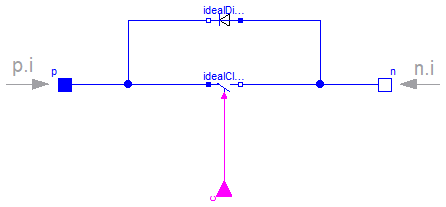
This model represents and idealized current bi-directional switch. This is the typical IGBT in anti-parallel with a diode from which many converters are built.
Extends from Modelica.Electrical.Analog.Interfaces.TwoPin (Component with two electrical pins).
| Type | Name | Description |
|---|---|---|
| PositivePin | p | Positive pin Positive pin (potential p.v > n.v for positive voltage drop v) |
| NegativePin | n | Negative pin |
| input BooleanInput | c |
 PVSystems.Electrical.SW1
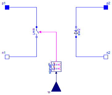
Switched model implemented with switch + diode
Extends from Interfaces.SwitchNetworkInterface (Interface for the averaged switch network models).
| Type | Name | Default | Description |
|---|---|---|---|
| Real | dmin | 1e-3 | Minimum duty cycle [1] |
| Real | dmax | 1 | Maximum duty cycle [1] |
| Real | dMax | 1 | Maximum duty cycle |
| Real | dMin | 0 | Minimum duty cycle |
| Frequency | fs | Switching frequency [Hz] | |
| Time | startTime | 0 | Start time [s] |
| Resistance | RD | 1.E-5 | Forward state-on differential resistance (closed resistance) [Ohm] |
| Voltage | VD | 0 | Forward threshold voltage [V] |
| Resistance | Ron | 1.E-5 | Closed switch resistance [Ohm] |
| Type | Name | Description |
|---|---|---|
| PositivePin | p1 | Positive pin of the left port (potential p1.v > n1.v for positive voltage drop v1) |
| NegativePin | n1 | Negative pin of the left port |
| PositivePin | p2 | Positive pin of the right port (potential p2.v > n2.v for positive voltage drop v2) |
| NegativePin | n2 | Negative pin of the right port |
| input RealInput | d | Duty cycle |
PVSystems.Electrical.SW2
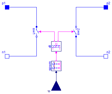
Switched model implemented with switch x 2
Extends from Interfaces.SwitchNetworkInterface (Interface for the averaged switch network models).
| Type | Name | Default | Description |
|---|---|---|---|
| Real | dmin | 1e-3 | Minimum duty cycle [1] |
| Real | dmax | 1 | Maximum duty cycle [1] |
| Real | dMax | 1 | Maximum duty cycle |
| Real | dMin | 0 | Minimum duty cycle |
| Frequency | fs | Switching frequency [Hz] | |
| Time | startTime | 0 | Start time [s] |
| Resistance | RD | 1.E-5 | Forward state-on differential resistance (closed resistance) [Ohm] |
| Voltage | VD | 0 | Forward threshold voltage [V] |
| Resistance | Ron | 1.E-5 | Closed switch resistance [Ohm] |
| Time | deadTime | 0 | Dead time [s] |
| Type | Name | Description |
|---|---|---|
| PositivePin | p1 | Positive pin of the left port (potential p1.v > n1.v for positive voltage drop v1) |
| NegativePin | n1 | Negative pin of the left port |
| PositivePin | p2 | Positive pin of the right port (potential p2.v > n2.v for positive voltage drop v2) |
| NegativePin | n2 | Negative pin of the right port |
| input RealInput | d | Duty cycle |
PVSystems.Electrical.SW3
Switched model implemented with switch + anti-parallel diode x 2

Extends from Interfaces.SwitchNetworkInterface (Interface for the averaged switch network models).
| Type | Name | Default | Description |
|---|---|---|---|
| Real | dmin | 1e-3 | Minimum duty cycle [1] |
| Real | dmax | 1 | Maximum duty cycle [1] |
| Real | dMax | 1 | Maximum duty cycle |
| Real | dMin | 0 | Minimum duty cycle |
| Frequency | fs | Switching frequency [Hz] | |
| Time | startTime | 0 | Start time [s] |
| Resistance | RD | 1.E-5 | Forward state-on differential resistance (closed resistance) [Ohm] |
| Voltage | VD | 0 | Forward threshold voltage [V] |
| Resistance | Ron | 1.E-5 | Closed switch resistance [Ohm] |
| Time | deadTime | 0 | Dead time [s] |
| Type | Name | Description |
|---|---|---|
| PositivePin | p1 | Positive pin of the left port (potential p1.v > n1.v for positive voltage drop v1) |
| NegativePin | n1 | Negative pin of the left port |
| PositivePin | p2 | Positive pin of the right port (potential p2.v > n2.v for positive voltage drop v2) |
| NegativePin | n2 | Negative pin of the right port |
| input RealInput | d | Duty cycle |
PVSystems.Electrical.CCM1
Average CCM model with no losses

Application: two-switch PWM converters.
Limitations: ideal switches, CCM only, no transformer.
Model taken from EM01 and EMA16.
Extends from Interfaces.SwitchNetworkInterface (Interface for the averaged switch network models).
| Type | Name | Default | Description |
|---|---|---|---|
| Real | dmin | 1e-3 | Minimum duty cycle [1] |
| Real | dmax | 1 | Maximum duty cycle [1] |
| Type | Name | Description |
|---|---|---|
| PositivePin | p1 | Positive pin of the left port (potential p1.v > n1.v for positive voltage drop v1) |
| NegativePin | n1 | Negative pin of the left port |
| PositivePin | p2 | Positive pin of the right port (potential p2.v > n2.v for positive voltage drop v2) |
| NegativePin | n2 | Negative pin of the right port |
| input RealInput | d | Duty cycle |
PVSystems.Electrical.CCM2
Average CCM model with conduction losses
Application: two-switch PWM converters, includes conduction losses due to Ron, VD, Rd.
Limitations: CCM only, no transformer.
Model taken from EM01 and EMA16.
Extends from Interfaces.SwitchNetworkInterface (Interface for the averaged switch network models).
| Type | Name | Default | Description |
|---|---|---|---|
| Real | dmin | 1e-3 | Minimum duty cycle [1] |
| Real | dmax | 1 | Maximum duty cycle [1] |
| Resistance | Ron | 0 | Transistor on resistance [Ohm] |
| Resistance | RD | 0 | Diode on resistance [Ohm] |
| Voltage | VD | 0 | Diode forward voltage drop [V] |
| Type | Name | Description |
|---|---|---|
| PositivePin | p1 | Positive pin of the left port (potential p1.v > n1.v for positive voltage drop v1) |
| NegativePin | n1 | Negative pin of the left port |
| PositivePin | p2 | Positive pin of the right port (potential p2.v > n2.v for positive voltage drop v2) |
| NegativePin | n2 | Negative pin of the right port |
| input RealInput | d | Duty cycle |
PVSystems.Electrical.CCM3
Average CCM model with no losses and tranformer
Application: two-switch PWM converters, with (possibly) transformer.
Limitations: ideal switches, CCM only.
Model taken from EM01 and EMA16.
Extends from Interfaces.SwitchNetworkInterface (Interface for the averaged switch network models).
| Type | Name | Default | Description |
|---|---|---|---|
| Real | dmin | 1e-3 | Minimum duty cycle [1] |
| Real | dmax | 1 | Maximum duty cycle [1] |
| Real | n | 1 | Transformer turns ratio 1:n (primary:secondary) [1] |
| Type | Name | Description |
|---|---|---|
| PositivePin | p1 | Positive pin of the left port (potential p1.v > n1.v for positive voltage drop v1) |
| NegativePin | n1 | Negative pin of the left port |
| PositivePin | p2 | Positive pin of the right port (potential p2.v > n2.v for positive voltage drop v2) |
| NegativePin | n2 | Negative pin of the right port |
| input RealInput | d | Duty cycle |
PVSystems.Electrical.CCM4
Average CCM model with conduction losses and tranformer
Application: two-switch PWM converters, includes conduction losses due to Ron, VD, RD and (possibly) transformer.
Limitations: CCM only.
Model taken from EM01 and EMA16.
Extends from Interfaces.SwitchNetworkInterface (Interface for the averaged switch network models).
| Type | Name | Default | Description |
|---|---|---|---|
| Real | dmin | 1e-3 | Minimum duty cycle [1] |
| Real | dmax | 1 | Maximum duty cycle [1] |
| Resistance | Ron | 0 | Transistor on resistance [Ohm] |
| Resistance | RD | 0 | Diode on resistance [Ohm] |
| Voltage | VD | 0 | Diode forward voltage drop [V] |
| Real | n | 1 | Transformer turns ratio 1:n (primary:secondary) [1] |
| Type | Name | Description |
|---|---|---|
| PositivePin | p1 | Positive pin of the left port (potential p1.v > n1.v for positive voltage drop v1) |
| NegativePin | n1 | Negative pin of the left port |
| PositivePin | p2 | Positive pin of the right port (potential p2.v > n2.v for positive voltage drop v2) |
| NegativePin | n2 | Negative pin of the right port |
| input RealInput | d | Duty cycle |
PVSystems.Electrical.CCM5
Average CCM model with conduction losses and diode reverse recovery
Application: two-switch PWM converters, includes conduction losses due to Ron, VD and diode reverse recovery losses.
Limitations: CCM only, d'>tr/Ts, <i1> > Qr/Ts.
Model taken from EM01 and EMA16.
Extends from Interfaces.SwitchNetworkInterface (Interface for the averaged switch network models).
| Type | Name | Default | Description |
|---|---|---|---|
| Real | dmin | 1e-3 | Minimum duty cycle [1] |
| Real | dmax | 1 | Maximum duty cycle [1] |
| Resistance | Ron | 0 | Transistor on resistance [Ohm] |
| Voltage | VD | 0 | Diode forward voltage drop [V] |
| Charge | Qr | Diode reverse recovery charge [C] | |
| Time | tr | Diode reverse recovery time [s] | |
| Frequency | fs | Switching frequency [Hz] |
| Type | Name | Description |
|---|---|---|
| PositivePin | p1 | Positive pin of the left port (potential p1.v > n1.v for positive voltage drop v1) |
| NegativePin | n1 | Negative pin of the left port |
| PositivePin | p2 | Positive pin of the right port (potential p2.v > n2.v for positive voltage drop v2) |
| NegativePin | n2 | Negative pin of the right port |
| input RealInput | d | Duty cycle |
PVSystems.Electrical.CCM_DCM1
Average CCM-DCM model with no losses
Application: two-switch PWM converters, CCM or DCM.
Limitations: ideal switches, no transformer.
Model taken from EM01 and EMA16.
Extends from Interfaces.SwitchNetworkInterface (Interface for the averaged switch network models).
| Type | Name | Default | Description |
|---|---|---|---|
| Real | dmin | 1e-3 | Minimum duty cycle [1] |
| Real | dmax | 1 | Maximum duty cycle [1] |
| Inductance | Le | Equivalent DCM inductance [H] | |
| Frequency | fs | Switching frequency [Hz] |
| Type | Name | Description |
|---|---|---|
| PositivePin | p1 | Positive pin of the left port (potential p1.v > n1.v for positive voltage drop v1) |
| NegativePin | n1 | Negative pin of the left port |
| PositivePin | p2 | Positive pin of the right port (potential p2.v > n2.v for positive voltage drop v2) |
| NegativePin | n2 | Negative pin of the right port |
| input RealInput | d | Duty cycle |
PVSystems.Electrical.CCM_DCM2
Average CCM-DCM model with no losses and transformer
Application: two-switch PWM converters, CCM or DCM with (possibly) transformer.
Limitations: ideal switches.
Model taken from EM01 and EMA16.
Extends from Interfaces.SwitchNetworkInterface (Interface for the averaged switch network models).
| Type | Name | Default | Description |
|---|---|---|---|
| Real | dmin | 1e-3 | Minimum duty cycle [1] |
| Real | dmax | 1 | Maximum duty cycle [1] |
| Inductance | Le | Equivalent DCM inductance [H] | |
| Frequency | fs | Switching frequency [Hz] | |
| Real | n | 1 | Transformer turns ratio 1:n (primary:secondary) [1] |
| Type | Name | Description |
|---|---|---|
| PositivePin | p1 | Positive pin of the left port (potential p1.v > n1.v for positive voltage drop v1) |
| NegativePin | n1 | Negative pin of the left port |
| PositivePin | p2 | Positive pin of the right port (potential p2.v > n2.v for positive voltage drop v2) |
| NegativePin | n2 | Negative pin of the right port |
| input RealInput | d | Duty cycle |
 PVSystems.Electrical.PVArray
Flexible PV array model
Flexible PV array model. The model can be parametrized with the use of PV module datasheets. As a default, the data from the Kyocera KC200GT is provided. The model is presented in "Comprehensive Approach to Modeling and Simulation of Photovoltaic Arrays" by M.G. Villalva et al.
Extends from Modelica.Electrical.Analog.Interfaces.OnePort (Component with two electrical pins p and n and current i from p to n).
| Type | Name | Default | Description |
|---|---|---|---|
| Current | Imp | 7.61 | Maximum power current [A] |
| Voltage | Vmp | 26.3 | Maximum power voltage [V] |
| Current | Iscn | 8.21 | Short circuit current [A] |
| Voltage | Vocn | 32.9 | Open circuit voltage [V] |
| Real | Kv | -0.123 | Voc temperature coefficient |
| Real | Ki | 3.18e-3 | Isc temperature coefficient |
| Real | Ns | 54 | Number of cells in series |
| Real | Np | 1 | Number of cells in parallel |
| Resistance | Rs | 0.221 | Equivalent series resistance of array [Ohm] |
| Resistance | Rp | 415.405 | Equivalent parallel resistance of array [Ohm] |
| Real | a | 1.3 | Diode ideality constant |
| Current | Ipvn | Iscn | Photovoltaic current at STC [A] |
| Type | Name | Description |
|---|---|---|
| PositivePin | p | Positive pin (potential p.v > n.v for positive voltage drop v) |
| NegativePin | n | Negative pin |
| input RealInput | G | Solar irradiation |
| input RealInput | T | Panel temperature |
 PVSystems.Electrical.SimpleBattery
Simple battery model
Extends from Interfaces.BatteryInterface (Partial model for battery).
| Type | Name | Default | Description |
|---|---|---|---|
| Resistance | Rint | 0.09 | Internal resistance [Ohm] |
| Voltage | E0 | 3.7348 | Constant battery voltage [V] |
| Voltage | K | 0.00876 | Polarization voltage [V] |
| Real | Q | 1 | Rated battery capacity [A.h] |
| Voltage | A | 0.468 | Exponential region amplitude [V] |
| Real | B | 3.5294 | Exponential zone time constant inverse |
| Real | DoDini | 0 | Initial Depth of Discharge [A.h] |
| Type | Name | Description |
|---|---|---|
| PositivePin | p | Positive pin (potential p.v > n.v for positive voltage drop v) |
| NegativePin | n | Negative pin |