 Modelica.Electrical.Analog.Interfaces.TwoPin
Modelica.Electrical.Analog.Interfaces.TwoPin
Modelica.Electrical.Analog.Interfaces.TwoPin
Component with two electrical pins
TwoPin is a partial model with two pins and one internal variable for the voltage over the two pins. Internal currents are not defined. It is intended to be used in cases where the model which inherits TwoPin is composed by combining other components graphically, not by equations.
| Type | Name | Description |
|---|---|---|
| PositivePin | p | Positive pin Positive pin (potential p.v > n.v for positive voltage drop v) |
| NegativePin | n | Negative pin |
Modelica.Electrical.Analog.Interfaces.OnePort
Component with two electrical pins p and n and current i from p to n
Superclass of elements which have two electrical pins: the positive pin connector p, and the negative pin connector n. It is assumed that the current flowing into pin p is identical to the current flowing out of pin n. This current is provided explicitly as current i.
| Type | Name | Description |
|---|---|---|
| PositivePin | p | Positive pin (potential p.v > n.v for positive voltage drop v) |
| NegativePin | n | Negative pin |
 Modelica.Electrical.Analog.Interfaces.PositivePin
Positive pin of an electric component
Connectors PositivePin and NegativePin are nearly identical. The only difference is that the icons are different in order to identify more easily the pins of a component. Usually, connector PositivePin is used for the positive and connector NegativePin for the negative pin of an electrical component.
| Type | Name | Description |
|---|---|---|
| Voltage | v | Potential at the pin [V] |
| flow Current | i | Current flowing into the pin [A] |
 Modelica.Electrical.Analog.Interfaces.NegativePin
Negative pin of an electric component
Connectors PositivePin and NegativePin are nearly identical. The only difference is that the icons are different in order to identify more easily the pins of a component. Usually, connector PositivePin is used for the positive and connector NegativePin for the negative pin of an electrical component.
| Type | Name | Description |
|---|---|---|
| Voltage | v | Potential at the pin [V] |
| flow Current | i | Current flowing into the pin [A] |
 Modelica.Electrical.Analog.Interfaces.VoltageSource
Interface for voltage sources
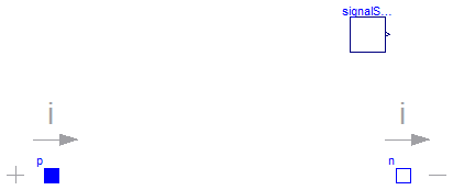
The VoltageSource partial model prepares voltage sources by providing the pins, and the offset and startTime parameters, which are the same at all voltage sources. The source behavior is taken from Modelica.Blocks signal sources by inheritance and usage of the replaceable possibilities.
Extends from OnePort (Component with two electrical pins p and n and current i from p to n).
| Type | Name | Default | Description |
|---|---|---|---|
| Voltage | offset | 0 | Voltage offset [V] |
| Time | startTime | 0 | Time offset [s] |
| SignalSource | signalSource | redeclare Modelica.Blocks.In... |
| Type | Name | Description |
|---|---|---|
| PositivePin | p | Positive pin (potential p.v > n.v for positive voltage drop v) |
| NegativePin | n | Negative pin |
 Modelica.Electrical.Analog.Interfaces.ConditionalHeatPort
Partial model to include a conditional HeatPort in order to describe the power loss via a thermal network

This partial model provides a conditional heating port for the connection to a thermal network.
If this model is used, the loss power has to be provided by an equation in the model which inherits from ConditionalHeatingPort model (lossPower = ...). As device temperature T_heatPort can be used to describe the influence of the device temperature on the model behaviour.
| Type | Name | Default | Description |
|---|---|---|---|
| Boolean | useHeatPort | false | =true, if heatPort is enabled |
| Temperature | T | 293.15 | Fixed device temperature if useHeatPort = false [K] |
| Type | Name | Description |
|---|---|---|
| HeatPort_a | heatPort | Conditional heat port |
 Modelica.Electrical.Analog.Interfaces.Pin
Pin of an electrical component

Pin is the basic electric connector. It includes the voltage which consists between the pin and the ground node. The ground node is the node of (any) ground device (Modelica.Electrical.Basic.Ground). Furthermore, the pin includes the current, which is considered to be positive if it is flowing at the pin into the device.
| Type | Name | Description |
|---|---|---|
| Voltage | v | Potential at the pin [V] |
| flow Current | i | Current flowing into the pin [A] |
 Modelica.Electrical.Analog.Interfaces.IdealSwitch
Ideal electrical switch
The ideal switch has a positive pin p and a negative pin n.
The switching behaviour is controlled by the boolean signal off.
If off is true, pin p is not connected with negative pin n.
Otherwise, pin p is connected with negative pin n.
In order to prevent singularities during switching, the opened
switch has a (very low) conductance Goff
and the closed switch has a (very low) resistance Ron.
The limiting case is also allowed, i.e., the resistance Ron of the
closed switch could be exactly zero and the conductance Goff of the
open switch could be also exactly zero. Note, there are circuits,
where a description with zero Ron or zero Goff is not possible.
Please note:
In case of useHeatPort=true the temperature dependence of the electrical
behavior is not modelled. The parameters are not temperature dependent.
Extends from Modelica.Electrical.Analog.Interfaces.OnePort (Component with two electrical pins p and n and current i from p to n), Modelica.Electrical.Analog.Interfaces.ConditionalHeatPort (Partial model to include a conditional HeatPort in order to describe the power loss via a thermal network).
| Type | Name | Default | Description |
|---|---|---|---|
| Resistance | Ron | 1.E-5 | Closed switch resistance [Ohm] |
| Conductance | Goff | 1.E-5 | Opened switch conductance [S] |
| Boolean | useHeatPort | false | =true, if heatPort is enabled |
| Temperature | T | 293.15 | Fixed device temperature if useHeatPort = false [K] |
| Type | Name | Description |
|---|---|---|
| PositivePin | p | Positive pin (potential p.v > n.v for positive voltage drop v) |
| NegativePin | n | Negative pin |
| HeatPort_a | heatPort | Conditional heat port |
 Modelica.Electrical.Analog.Interfaces.IdealSemiconductor
Ideal semiconductor
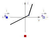
This is an ideal semiconductor which is
open (off), if it is reversed biased (voltage drop less than 0)
closed (on), if it is conducting (current > 0).
This is the behaviour if all parameters are exactly zero.
Note, there are circuits, where this ideal description
with zero resistance and zero conductance is not possible.
In order to prevent singularities during switching, the opened
semiconductor has a small conductance Gon
and the closed semiconductor has a low resistance Roff which is default.
The parameter Vknee which is the forward threshold voltage, allows to displace
the knee point
along the Gon-characteristic until v = Vknee.
Please note:
In case of useHeatPort=true the temperature dependence of the electrical
behavior is not modelled.
Extends from Modelica.Electrical.Analog.Interfaces.OnePort (Component with two electrical pins p and n and current i from p to n), Modelica.Electrical.Analog.Interfaces.ConditionalHeatPort (Partial model to include a conditional HeatPort in order to describe the power loss via a thermal network).
| Type | Name | Default | Description |
|---|---|---|---|
| Resistance | Ron | 1.E-5 | Forward state-on differential resistance (closed resistance) [Ohm] |
| Conductance | Goff | 1.E-5 | Backward state-off conductance (opened conductance) [S] |
| Voltage | Vknee | 0 | Forward threshold voltage [V] |
| Boolean | useHeatPort | false | =true, if heatPort is enabled |
| Temperature | T | 293.15 | Fixed device temperature if useHeatPort = false [K] |
| Type | Name | Description |
|---|---|---|
| PositivePin | p | Positive pin (potential p.v > n.v for positive voltage drop v) |
| NegativePin | n | Negative pin |
| HeatPort_a | heatPort | Conditional heat port |