Block assemblies useful in PV and power electronics
Information
Block assemblies useful in PV and power electronics
Extends from Icons.AssembliesPackage (Icon for packages of assemblies).
Package Content
| Name |
Description |
 Inverter1phCurrentController Inverter1phCurrentController
|
Simple synchronous reference frame PI current controller |
 Inverter1phCompleteController Inverter1phCompleteController
|
Complete synchronous reference frame inverter controller |
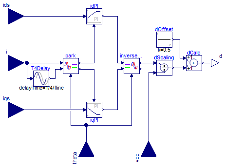
Simple synchronous reference frame PI current controller
Information
Synchronous reference frame current controller for a 1-phase
inverter. It takes the measured and the dq setpoints and
calculates the duty cycle, which can be then used as the input to
the SignalPWM
block in switching models or directly as the input of the switch
or converter in averaged models.
The control is performed with
two LimPID
blocks (one per component) configured as a PI controller.
Extends from Modelica.Blocks.Icons.Block (Basic graphical layout of input/output block).
Parameters
| Type | Name | Default | Description |
|---|
| Real | k | 0.1 | PI controllers gain [1] |
| Time | T | 0.01 | PI controllers time constant (T>0 required) [s] |
| Frequency | fline | 50 | AC line frequency [Hz] |
| Real | idMax | Modelica.Constants.inf | Maximum effort for id loop |
| Real | iqMax | Modelica.Constants.inf | Maximum effort for iq loop |
Connectors
Modelica definition
block Inverter1phCurrentController
extends Modelica.Blocks.Icons.Block;
parameter Real k(
final unit="1") = 0.1 ;
parameter Modelica.SIunits.Time T(
final min=Modelica.Constants.small) = 0.01
;
parameter Modelica.SIunits.Frequency fline=50 ;
parameter Real idMax=Modelica.Constants.inf ;
parameter Real iqMax=Modelica.Constants.inf ;
Park park;
Modelica.Blocks.Nonlinear.FixedDelay T4Delay(delayTime=1/4/fline);
Modelica.Blocks.Continuous.LimPID idPI(
k=k,
controllerType=Modelica.Blocks.Types.SimpleController.PI,
Ti=T,
yMax=idMax);
Modelica.Blocks.Continuous.LimPID iqPI(
k=k,
controllerType=Modelica.Blocks.Types.SimpleController.PI,
Ti=T,
yMax=iqMax);
InversePark inversePark;
Modelica.Blocks.Sources.Constant dOffset(k=0.5);
Modelica.Blocks.Interfaces.RealInput i ;
Modelica.Blocks.Interfaces.RealInput ids ;
Modelica.Blocks.Interfaces.RealInput iqs ;
Modelica.Blocks.Interfaces.RealInput theta ;
Modelica.Blocks.Interfaces.RealInput vdc ;
Modelica.Blocks.Interfaces.RealOutput d ;
Modelica.Blocks.Math.Division dScaling;
Modelica.Blocks.Math.Add dCalc;
equation
connect(park.beta, T4Delay.y);
connect(iqPI.y, inversePark.q);
connect(idPI.y, inversePark.d);
connect(i, park.alpha);
connect(i, T4Delay.u);
connect(inversePark.theta, theta);
connect(inversePark.alpha, dScaling.u1);
connect(vdc, dScaling.u2);
connect(dScaling.y, dCalc.u2);
connect(dCalc.y, d);
connect(theta, park.theta);
connect(dOffset.y, dCalc.u1);
connect(idPI.u_s, ids);
connect(idPI.u_m, park.d);
connect(park.q, iqPI.u_m);
connect(iqPI.u_s, iqs);
end Inverter1phCurrentController;
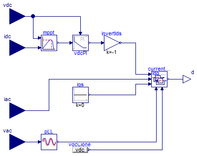
Complete synchronous reference frame inverter controller
Information
An
additional LimPID
block is used to closed the DC voltage loop around the d
component of the AC current,
using Inverter1phCurrentController.
Currently, this block doesn't provide control of the q
component, which is set to 0.
Extends from Modelica.Blocks.Icons.Block (Basic graphical layout of input/output block).
Parameters
| Type | Name | Default | Description |
|---|
| Real | ik | 0.1 | Current PI gain |
| Time | iT | 0.01 | Current PI time constant [s] |
| Real | idMax | Modelica.Constants.inf | Maximum effort for id loop |
| Real | iqMax | Modelica.Constants.inf | Maximum effort for iq loop |
| Real | vk | 0.1 | Voltage PI gain |
| Time | vT | 0.01 | Voltage PI time constant [s] |
| Real | vdcMax | Modelica.Constants.inf | Maximum effort for vdc loop |
| Frequency | fline | 50 | Line frequency [Hz] |
Connectors
Modelica definition
block Inverter1phCompleteController
extends Modelica.Blocks.Icons.Block;
parameter Real ik=0.1 ;
parameter Modelica.SIunits.Time iT=0.01 ;
parameter Real idMax=Modelica.Constants.inf ;
parameter Real iqMax=Modelica.Constants.inf ;
parameter Real vk=0.1 ;
parameter Modelica.SIunits.Time vT=0.01 ;
parameter Real vdcMax=Modelica.Constants.inf ;
parameter Modelica.SIunits.Frequency fline=50 ;
Modelica.Blocks.Interfaces.RealInput iac ;
Modelica.Blocks.Interfaces.RealInput vac ;
Modelica.Blocks.Interfaces.RealInput idc ;
Modelica.Blocks.Interfaces.RealInput vdc ;
Modelica.Blocks.Interfaces.RealOutput d ;
Modelica.Blocks.Sources.Constant iqs(k=0);
PVSystems.Control.MPPTController mppt(
sampleTime=1,
vrefStep=0.5,
pkThreshold=0.5,
vrefStart=15);
Modelica.Blocks.Continuous.LimPID vdcPI(
k=vk,
controllerType=Modelica.Blocks.Types.SimpleController.PI,
Ti=vT,
yMax=vdcMax);
Inverter1phCurrentController currentController(
k=ik,
T=iT,
fline=fline,
idMax=idMax,
iqMax=iqMax);
PLL pLL(frequency=fline);
Modelica.Blocks.Sources.RealExpression vdcClone(y=vdc);
Modelica.Blocks.Math.Gain invertIds(k=-1);
equation
connect(currentController.d, d);
connect(idc, mppt.u2);
connect(vdc, mppt.u1);
connect(iac, currentController.i);
connect(iqs.y, currentController.iqs);
connect(vac, pLL.v);
connect(pLL.theta, currentController.theta);
connect(vdcClone.y, currentController.vdc);
connect(mppt.y, vdcPI.u_s);
connect(vdc, vdcPI.u_m);
connect(vdcPI.y, invertIds.u);
connect(invertIds.y, currentController.ids);
end Inverter1phCompleteController;
Automatically generated Mon Sep 11 16:11:49 2017.
 PVSystems.Control.Assemblies.Inverter1phCurrentController
 PVSystems.Control.Assemblies.Inverter1phCompleteController