 Modelica.Blocks.Sources.RealExpression
Modelica.Blocks.Sources.RealExpression
Modelica.Blocks.Sources.RealExpression
Set output signal to a time varying Real expression

The (time varying) Real output signal of this block can be defined in its parameter menu via variable y. The purpose is to support the easy definition of Real expressions in a block diagram. For example, in the y-menu the definition "if time < 1 then 0 else 1" can be given in order to define that the output signal is one, if time ≥ 1 and otherwise it is zero. Note, that "time" is a built-in variable that is always accessible and represents the "model time" and that Variable y is both a variable and a connector.
| Type | Name | Default | Description |
|---|---|---|---|
| Time varying output signal | |||
| RealOutput | y | 0.0 | Value of Real output |
| Type | Name | Description |
|---|---|---|
| Time varying output signal | ||
| output RealOutput | y | Value of Real output |
 Modelica.Blocks.Sources.Sine
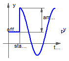
Generate sine signal
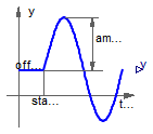
The Real output y is a sine signal:
/Dymola%202017%20FD01/Modelica/Library/Modelica%203.2.2/Resources/Images/Blocks/Sources/Sine.png)
Extends from Interfaces.SO (Single Output continuous control block).
| Type | Name | Default | Description |
|---|---|---|---|
| Real | amplitude | 1 | Amplitude of sine wave |
| Frequency | freqHz | Frequency of sine wave [Hz] | |
| Angle | phase | 0 | Phase of sine wave [rad] |
| Real | offset | 0 | Offset of output signal |
| Time | startTime | 0 | Output = offset for time < startTime [s] |
| Type | Name | Description |
|---|---|---|
| output RealOutput | y | Connector of Real output signal |
 Modelica.Blocks.Sources.Constant
Generate constant signal of type Real
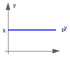
The Real output y is a constant signal:
/Dymola%202017%20FD01/Modelica/Library/Modelica%203.2.2/Resources/Images/Blocks/Sources/Constant.png)
Extends from Interfaces.SO (Single Output continuous control block).
| Type | Name | Default | Description |
|---|---|---|---|
| Real | k | Constant output value |
| Type | Name | Description |
|---|---|---|
| output RealOutput | y | Connector of Real output signal |
 Modelica.Blocks.Sources.Step
Generate step signal of type Real
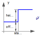
The Real output y is a step signal:
/Dymola%202017%20FD01/Modelica/Library/Modelica%203.2.2/Resources/Images/Blocks/Sources/Step.png)
Extends from Interfaces.SignalSource (Base class for continuous signal source).
| Type | Name | Default | Description |
|---|---|---|---|
| Real | height | 1 | Height of step |
| Real | offset | 0 | Offset of output signal y |
| Time | startTime | 0 | Output y = offset for time < startTime [s] |
| Type | Name | Description |
|---|---|---|
| output RealOutput | y | Connector of Real output signal |
 Modelica.Blocks.Sources.SawTooth
Generate saw tooth signal
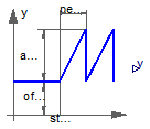
The Real output y is a saw tooth signal:
/Dymola%202017%20FD01/Modelica/Library/Modelica%203.2.2/Resources/Images/Blocks/Sources/SawTooth.png)
Extends from Interfaces.SO (Single Output continuous control block).
| Type | Name | Default | Description |
|---|---|---|---|
| Real | amplitude | 1 | Amplitude of saw tooth |
| Time | period | Time for one period [s] | |
| Integer | nperiod | -1 | Number of periods (< 0 means infinite number of periods) |
| Real | offset | 0 | Offset of output signals |
| Time | startTime | 0 | Output = offset for time < startTime [s] |
| Type | Name | Description |
|---|---|---|
| output RealOutput | y | Connector of Real output signal |
 Modelica.Blocks.Sources.Cosine
Generate cosine signal
The Real output y is a cosine signal:
/Dymola%202017%20FD01/Modelica/Library/Modelica%203.2.2/Resources/Images/Blocks/Sources/Cosine.png)
Extends from Interfaces.SO (Single Output continuous control block).
| Type | Name | Default | Description |
|---|---|---|---|
| Real | amplitude | 1 | Amplitude of cosine wave |
| Frequency | freqHz | Frequency of cosine wave [Hz] | |
| Angle | phase | 0 | Phase of cosine wave [rad] |
| Real | offset | 0 | Offset of output signal |
| Time | startTime | 0 | Output = offset for time < startTime [s] |
| Type | Name | Description |
|---|---|---|
| output RealOutput | y | Connector of Real output signal |
 Modelica.Blocks.Sources.Ramp
Generate ramp signal
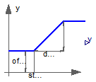
The Real output y is a ramp signal:
/Dymola%202017%20FD01/Modelica/Library/Modelica%203.2.2/Resources/Images/Blocks/Sources/Ramp.png)
If parameter duration is set to 0.0, the limiting case of a Step signal is achieved.
Extends from Interfaces.SO (Single Output continuous control block).
| Type | Name | Default | Description |
|---|---|---|---|
| Real | height | 1 | Height of ramps |
| Time | duration | Duration of ramp (= 0.0 gives a Step) [s] | |
| Real | offset | 0 | Offset of output signal |
| Time | startTime | 0 | Output = offset for time < startTime [s] |
| Type | Name | Description |
|---|---|---|
| output RealOutput | y | Connector of Real output signal |
 Modelica.Blocks.Sources.BooleanExpression
Set output signal to a time varying Boolean expression

The (time varying) Boolean output signal of this block can be defined in its parameter menu via variable y. The purpose is to support the easy definition of Boolean expressions in a block diagram. For example, in the y-menu the definition "time >= 1 and time <= 2" can be given in order to define that the output signal is true in the time interval 1 ≤ time ≤ 2 and otherwise it is false. Note, that "time" is a built-in variable that is always accessible and represents the "model time" and that Variable y is both a variable and a connector.
| Type | Name | Default | Description |
|---|---|---|---|
| Time varying output signal | |||
| BooleanOutput | y | false | Value of Boolean output |
| Type | Name | Description |
|---|---|---|
| Time varying output signal | ||
| output BooleanOutput | y | Value of Boolean output |
 Modelica.Blocks.Sources.BooleanStep
Generate step signal of type Boolean
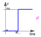
The Boolean output y is a step signal:
/Dymola%202017%20FD01/Modelica/Library/Modelica%203.2.2/Resources/Images/Blocks/Sources/BooleanStep.png)
Extends from Interfaces.partialBooleanSource (Partial source block (has 1 output Boolean signal and an appropriate default icon)).
| Type | Name | Default | Description |
|---|---|---|---|
| Time | startTime | 0 | Time instant of step start [s] |
| Boolean | startValue | false | Output before startTime |
| Type | Name | Description |
|---|---|---|
| output BooleanOutput | y | Connector of Boolean output signal |
 Modelica.Blocks.Sources.BooleanPulse
Generate pulse signal of type Boolean
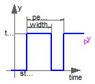
The Boolean output y is a pulse signal:
/Dymola%202017%20FD01/Modelica/Library/Modelica%203.2.2/Resources/Images/Blocks/Sources/Pulse.png)
Extends from Modelica.Blocks.Interfaces.partialBooleanSource (Partial source block (has 1 output Boolean signal and an appropriate default icon)).
| Type | Name | Default | Description |
|---|---|---|---|
| Real | width | 50 | Width of pulse in % of period |
| Time | period | Time for one period [s] | |
| Time | startTime | 0 | Time instant of first pulse [s] |
| Type | Name | Description |
|---|---|---|
| output BooleanOutput | y | Connector of Boolean output signal |